info@avatto.com
+91-9920808017
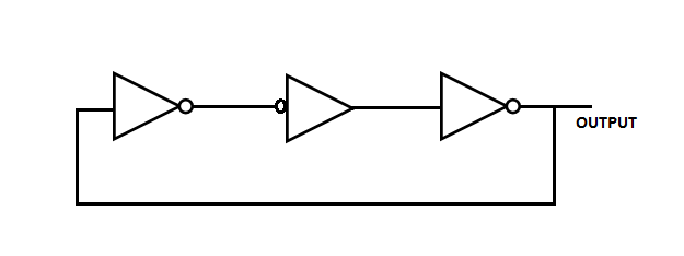
56. The circuit shown in the figure given below
is an oscillating circuit and its output is a square wave
is one whose output remains stable in ' 1 ' state
is one having output remains stable ' 0 ' state
having a single pulse of 3 times propagation delay
Your email address will not be published. Required fields are marked *
Report
Name
Email
Website
Save my name, email, and website in this browser for the next time I comment.
Comment
57. In the circuit shown below the input data is fixed at a LOW level and the output values are as shown in the figure. The number of lock pulses required to give an output of Φ Φ Φ Φ is
2
3
4
5
58. In the figure given below if Initially all flip-flops are cleared then how many clock pulses have to be applied to the system before the output from FF3 becomes a HIGH level?
6
8
59. The inputs of the J-K flip-flop, are PRESET = CLEAR = 1 : J = K = 0 If a single clock pulse is applied, then device will
toggle
set
reset
not change states
60. The logic circuit shown below is a 32-bit
shift register
asynchronous binary up counter
asynchronous binary down counter
synchronous binary up counter
Login with Facebook
Login with Google
Forgot your password?
Lost your password? Please enter your email address. You will receive mail with link to set new password.
Back to login