The correct state sequence of the circuit with initial state Q0=1, Q1Q2 = 0. The state of the circuit is given by the value 4Q2+ 2 Q1+Q0.
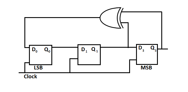
| A. | 1, 3, 4, 6, 7, 5, 2 |
| B. | 1, 2, 5, 3, 7, 6, 4 |
| C. | 1, 2, 7, 3, 5, 6, 4 |
| D. | 1, 6, 5, 7, 2, 3, 4 |
|
Option: D Explanation : Click on Discuss to view users comments. |
What is the modulo (number of pressing states) of the counter shown below
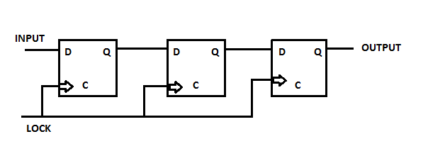
| A. | 3 |
| B. | 6 |
| C. | 8 |
| D. | Modulo cannot be determined from the circuit |
|
Option: A Explanation : Click on Discuss to view users comments. |
If a single clock pulse is applied, and following inputs are given to the J-K flip flop, then device will
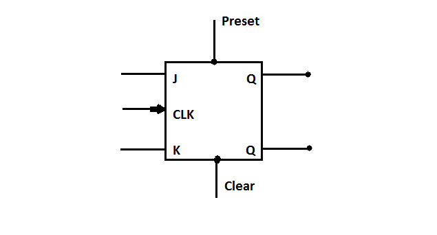
| A. | toggle |
| B. | set |
| C. | reset |
| D. | not change states |
|
Option: D Explanation : Click on Discuss to view users comments. |
The logic circuit shown below operates as a :
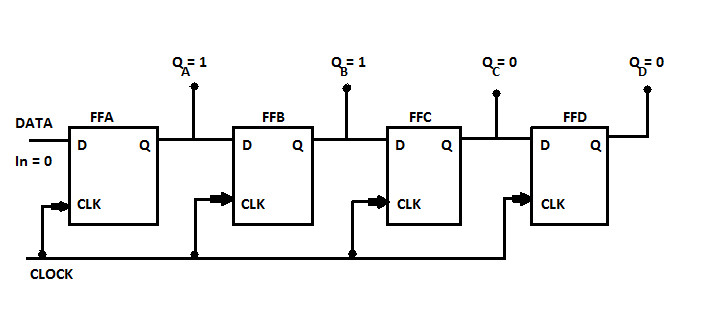
| A. | 4-bit asynchronous counter |
| B. | 4-bit synchronous counter |
| C. | BCD counter |
| D. | Serial-In Serial-Out shift register |
|
Option: B Explanation : Click on Discuss to view users comments. Shefali said: (6:26pm on Tuesday 13th March 2018)
It should be synchronus counter because same clock pulse is to all filp flops
|


