The logic circuit shown below is a 32-bit
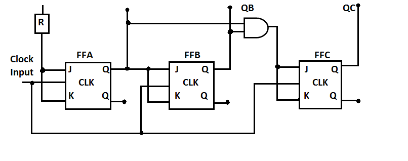
| A. | shift register |
| B. | asynchronous binary up counter |
| C. | asynchronous binary down counter |
| D. | synchronous binary up counter |
Answer : D Explanation : |
|
|
Option: A Explanation : Explanation will come here. Explanation will come here. Explanation will come here. Explanation will come here. Explanation will come here. |

